

- Counting Machines
- REA Verifier
- X-Rite
- TMI
- Printing and Packaging
- Chemical Testing Analysis
- Tisch/AADCO
Mobile:13926416086
Fax:020-32032628
Products
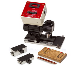
The tester is a motor-driven instrument for moving a weighted test strip over a printed specimen through an arc. The SUTHERLAND® 2000™ Ink Rub Tester, the industry standard for decades, has recently undergone some significant changes to enhance its utility and reliability. Combined with a new ASTM (American Society for Testing and Materials) recommended practice for its use, the Tester is an excellent position to enjoy even more widespread use in the coming years. The result of this work is an affordable abrasion-testing instrument that retains all the features that made it an industry standard plus improvements that ensure it will remain the industry standard in the new millennium. The cover shows the new tester.
In 1990 the stroke of the SUTHERLAND® 2000™ Ink Rub Tester was shortened, which increased the precision and more closely simulates abrasion damage found in the field. Research and other published work in the print-abrasion-testing arena have shown that quick strokes simulate some types of rub damage (most notably shipping damage). One of the biggest problems with the use of the SUTHERLAND® 2000™ had been the lack of a well-publicized test procedure for its use. While a procedure is available with the instrument, there was no nationally available method that could be readily referenced. This has now been corrected with the introduction by ASTM of ASTM D-5264 Ð 92, Standard Practice for Abrasion Resistance of Printed Materials by the SUTHERLAND® 2000™ Ink Rub Tester (copies available from ASTM). the proper procedure for using the SUTHERLAND® 2000™ Tester. Included in this method is the recommendation to use standard receptors of known abrasiveness when conducting a test.
The hold down bracket and clips are not shipped pre-installed on the unit because the ends of the wing nuts would tear at the shipping container, possibly allowing damage to the unit. This item is easily installed and only requires installation one time. Refer to the page called “Hold Down for Stock Test Specimen.” 1) Gently tip the unit on the side as shown. This will not damage the unit as long as it is done gently. 2) Remove the two rubber feet by gently twisting and pulling the feet. Remove the wing nuts and the hold down clips from the bracket with the two holes (this makes installation easier). Hold the bracket in place so that the holes are lined up with the holes on the base and with the studs towards the end of the unit. While holding the bracket in place replace the feet into the holes (a gentle twist maybe necessary to seat the feet). 3) Gently tip the unit back to the operating position. Install the hold down clips with the wing nuts. The hold down bracket is designed so that it can move slightly, adjusts the bracket so it is even with the end of the unit. The printed material can now be placed on the pad and the hold down hooks adjusted to hold pressure on the material to keep it from sliding. Caution – Do not use excessive pressure to hold material in place as it could cause the material to not lay completely flat. Use only enough pressure to hold the material in place.
I. Plug in the power cord to the correct voltage, the display will read a version number such as 1-0. If the machine is already plugged in, touching any key will reactivate the display to whatever the previous setting was. For all speed 1 low count rub tests, cycle the machine one time to allow the machine to reset the exact stroke. Note: If you leave the machine sit idle, after approximately 60 minutes it will automatically turn the display off.
II. COUNT BUTTON. Each time the COUNT button is pressed the displayed cycle counts will increase by one. When the COUNT button is held down, the counts will increase each ½ second. When the count reaches 10, it will start incrementing by 10's. When the count reaches 100 it will start incrementing by 100's. Anytime the button is released; the process will start over. (i.e. ones, tens, hundreds). While the motor is running the COUNT button is deactivated and “count” adjustments cannot be made. Maximum count is 999. Press “Reset” to remove the count number readout. If the motor is running, pressing the reset will also stop the motor and remove the count number to 000. Note: When adjusting the cycle count, the displayed value is the starting point, not the cycle count previously set. If the cycle count is 100 and the motor is started and then stopped at 95, pressing the COUNT button will set the cycle count to 96.
III. START AND STOP BUTTON. This controls the starting and stopping of the motor. After the count has reached 0’s, the motor will stop and after a short delay the display will reset back to the number that was displayed at the time of the last start cycle. If the motor is running when the START/STOP button is pressed, the motor will stop. The display is not cleared. Pressing START/STOP will start the motor again and the count will continue from the point at which the motor was stopped. Note: The motor will not start if the display reads 0’s.
IV. MOTOR SPEED BUTTON. Pressing the SPEED button will increment the motor through speed 1-4. The speed is indicated by one of the four LED lights. The speed available for testing are: Speed 1 (21 cycles per minute), Speed 2 (42 cycles per minute), speed 3 (85 cycles per minute), and Speed 4 (106 cycles per minute). When the machine is first plugged in it will automatically default to low speed (i.e. Speed 1) unless you press the SPEED button. The motor’s speed may be changed at any time, before starting the motor or after it is running. The speed of the motor is retained when the “Reset” button is pressed, to change speed press the SPEED button.
V. RESET BUTTON. This button will reset the count of the board. When pressed, the display will reset to 0’s. If the motor is running, the motor will shut off. This button may be pressed at any time.
The test requires two pieces of stock, the test specimen and a test receptor. Cut a test specimen, approximately six by three inches. When printed area permits, the sin inch directions should be cut across the grain of the sheet, but must not cross pressed or cut scores.
Prepare test strips of material from the same shipment of stock used in the test sample. Cleanly cut 2 X 7 inch strips for the four-pound weight are prepared by placing the strip face down against the pin of the scoring device and scoring at the white dot positions to facilitate bending the strip to conform to the test block.
To prepare samples for the two-pound weight, 2 X 5 ¼ inch strips are placed face down against the end pin of the scoring devise an scored at the red dot position to facilitate bending the strip to conform to the test weight (See picture tutorial “Test Specimen”).

